ZI 1037
Standards:EN 196-1, 459-2, 1015-11, 13454-2; ASTM C109, C348, C349; BS 3892-1, 4551-1
Specification:
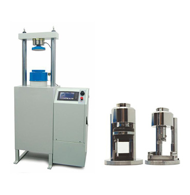
The Automatic Cement Compression & Flexural Testing Machine having single or double testing chamber are designed for reliable and consistent testing of mortar samples. These compression and flexure testers are the results of continuous applications and research studies to upgrade the machines with the latest technologies and conform the current standards in terms of its technical properties taking into account client requirements by using suitable accessories. These machines also meet the requirements of CE norms for safety and health of the operator. Compression and flexture jigs, distance pieces, and also removable transparent front-rear safety doors (should be factory installed) should be ordered separately. The automatic cement compression and flexure testing machines allow less experienced operators to perform the tests.
Once the machine has been switched on and the specimen is positioned and centered by the help of centering apparatus. The automatic cement compression and flexure testing machines consist of very rigid two column single or double chamber frames, automatic hydraulic power pack with data acquisition and control system.
Power Pack
Automatic Hydraulic Power Pack, dual stage, controlled by control panel is designed to supply the required oil to the load frames for loading. Very silent power pack can load the specimen between 50 N/sec to 2.4 kN/sec with an accuracy of ±5%. A Rapid approach pump is supplied as standard. Safety valve (maximum pressure valve) is used to avoid machine overloading.
Motor
The motor which drives the dual pump is an AC motor, 380 V, 50-60 Hz, 3 phase, 1 hp and 0.75 kW and it is controlled by motor inverter. The variation in the oil flow is executed with the variation of the rotation speed of the motor.
Distribution Block
A distribution block is used to control the oil flow direction supplied by the dual stage pump, the following parts are fitted to the distribution block;
a - Solenoid valve
b - Safety valve (maximum pressure valve)
c - Transducer
d - Low pressure gear pump
e - High pressure radial piston pump
Dual Stage Pump
The dual stage pump is formed by two groups
Low pressure gear pump
High pressure radial piston pump.
On the dual stage pump, a high delivery, low pressure gear pump is used for rapid approach, while a low delivery, high pressure radial piston pump is used for test execution. The Rapid approach facility shortens the time interval from piston start until the upper platen touches to the specimen. This excellent feature helps to save a lot of time when a large number of specimens are going to be tested.
Oil Tank
The tank includes enough oil to fill the mechanism which pushes the ram during the test. The level and oil temperature can be seen on the indicator fitted to the tank. It has 20 L capacity. Hydraulic motor oil, number 46, must be used.
Dimensions : 360 x 380 x 900 mm
Weight (approx.) : 80 kg
Power : 750 W
Control Unit
Control Unit is designed to control the machine and processing of data from load cells and pressure transducers which are fitted to the machine. All the operations of control unit are controlled from the front panel consisting of a 800x480 pixel 65535 color resistive touch screen display and function keys 2 analogue channels are provided for load-cells or pressure transducers. Control unit has easy to use menu options. The control unit’s digital graphic display is able to draw real-time "Load vs. Time", or "Stress vs. Time" graphics. Control unit unit offers many addition unique features. You can save more than 10000 test results in its internal memory. Control unit has support for various off-the-shelf USB printers. Thanks to its built-in internet protocol suite, every aspect of control unit device can be controlled remotely from anywhere around the world.
Maximum horizontal clearance for placing sample is limited with the border of the platens. Sample must be placed such that its ends will not overlap the ends of platens and it must be centered perfectly. The suitable vertical clearance for specimen can be adjusted with distance pieces.
| Model | ZI 1037 | ZI 1038 | ZI 1038 |
| Test Type | Compression | Flexure | Compression |
| Capacity | 250 kN | 15 kN | 250 kN |
| Class 1 Measuring Range | 2.5 to 250 kN | 0.5 to 15 kN | 2.5 to 250 kN |
| The roughness value for texture of loading and auxiliary platens | ≤3.2 μm | ≤3.2 μm | ≤3.2 μm |
| Lower Platen Dimensions | 165 mm | 165 mm | 165 mm |
| Upper Platen Dimensions | 165 mm | 165 mm | 165 mm |
| Maximum Vertical Clearance Between Platens | 263 mm | 263 mm | 263 mm |
| Piston Diameter | 160 mm | 80 mm | 160 mm |
| Maximum Piston Movement | 50 mm | 50 mm | 50 mm |
| Horizontal Clearance | 300 mm | 200 mm | 300 mm |
| Power | 750 W | 750 W | 750 W |
| Oil Capacity | 20 L | 20 L | 20 L |
| Maximum Working Pressure | 125 bar | 30 bar | 125 bar |
| Rapid Approach Rate | 50 mm/min | 80 mm/min | 50 mm/min |
| Dimensions (WxLxH) | 830x500x 1650 mm |
1050x500x 1650 mm |
1050x500x 1650 mm |
| Weight | 265 kg | 410 kg | 410 kg |